After two cans of aerosol carb cleaner, here's what the carb looks like:
And, after 1.5 hours (and 3/4 gallon of Castrol cleaner) with some bristle brush work and a hose:
|

|
This page contains many pictures of the installation,
and will take a long time to fully load. Click on any picture for
a larger, more detailed version.
|
[Edit Jun2023: This was a page I wrote around 2000, about my installation of a Pertronix "Ignitor" electronic ignition module, which eliminates ignition points and condenser. I chose to retain the OEM ignition coil. In response to a question from a reader, I see now that I did not explain the goal back then. The OEM ignition system has a ignition coil which runs at approximatetly 7-9v, and is fed via a ballast wire (ie wire that contains a resistor) that runs from the ignition switch to the coil. In their installation instructions, Pertronix was cagey about this: the installation instructions say to leave the ballast alone and feed the Ignitor module from this reduced voltage, but in an email I received they also said the Ignitor needs 8v to operate reliably. Therefore, in order to reliably feed the Ignitor, I installed a "ballast bypass" wire from the ignition switch to the Ignitor, and left the OEM ballasted wire to the OEM coil alone. Most of the last section of this page is devoted to that. On the Falcon, there is not a simple way to find switched 12v under the hood that is also not powered by the Accessory circuit, and it's undesireable to power the Ignitor when the ignition switch is in the Accessory position. Hopefully, this clarifies this page's purpose.] |
Installation
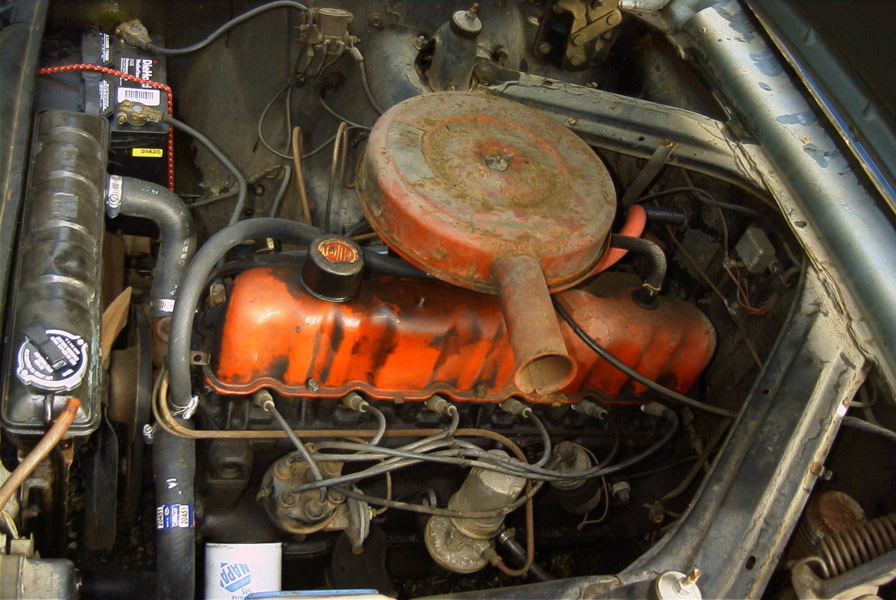
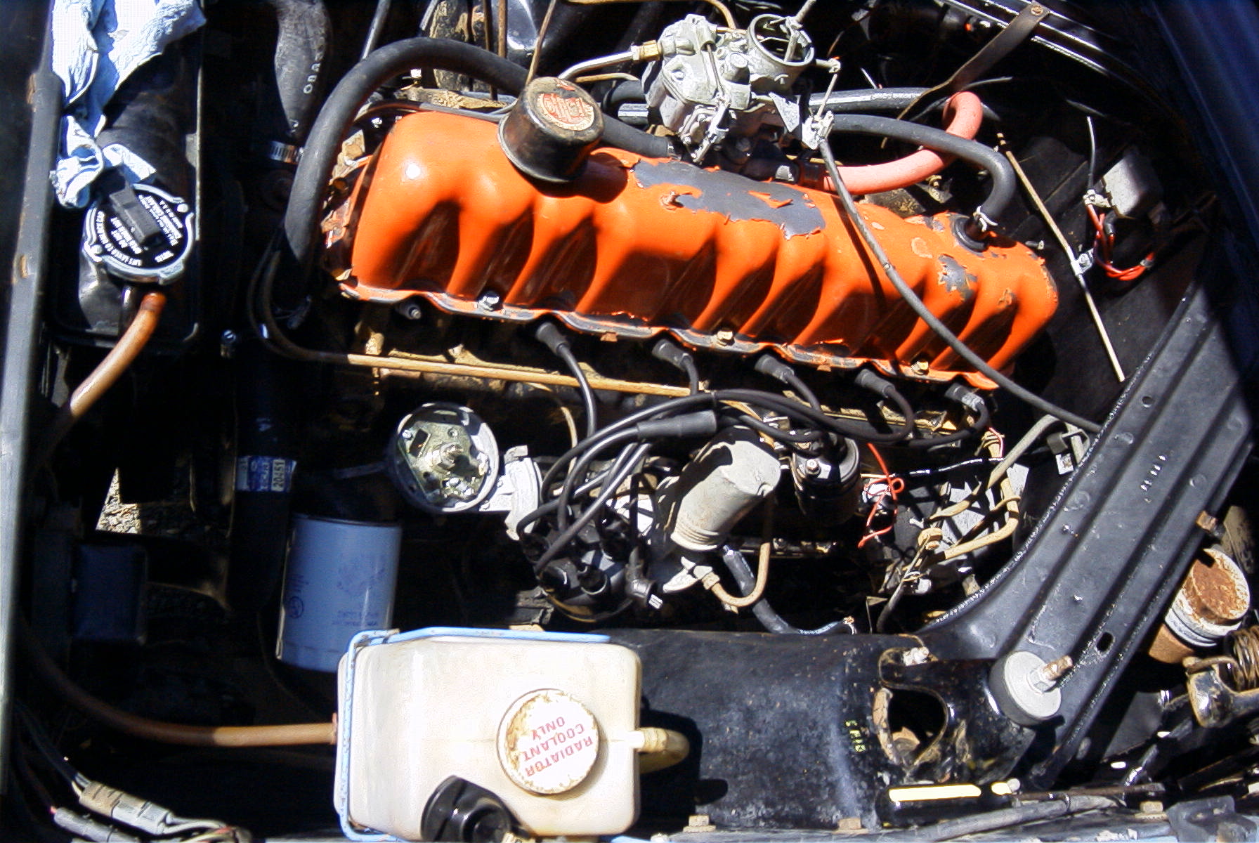
This is a '63 Falcon 170ci with FordOMatic. This is an one-owner,
86k miles California rig, but it's been sitting for 11 years and it's obviously
pretty dirty under the hood.
|
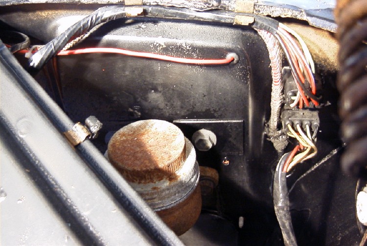
Here's the "before" picture:
|
||
|
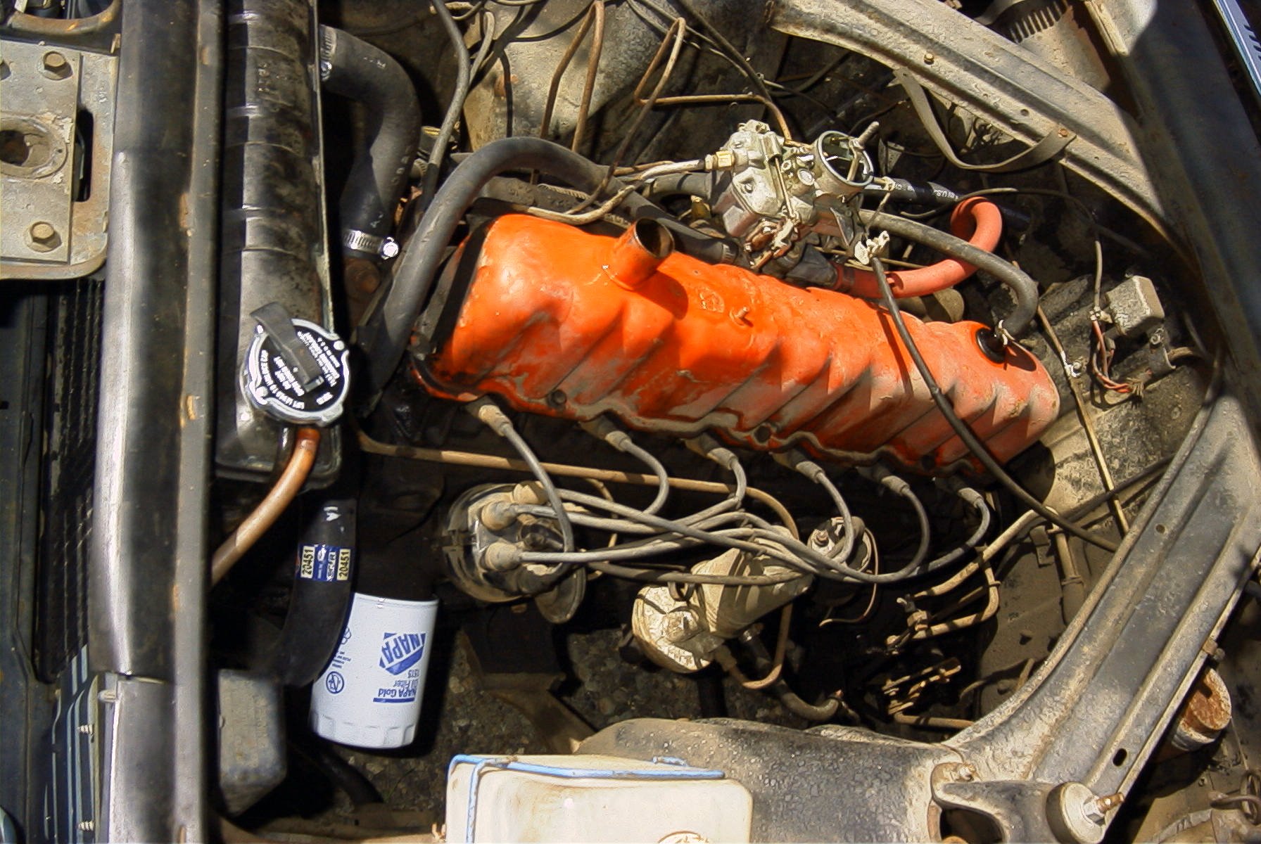
After two cans of aerosol carb cleaner, here's what the carb looks like:
|
||
|
And, after 1.5 hours (and 3/4 gallon of Castrol cleaner) with some bristle brush work and a hose:
|
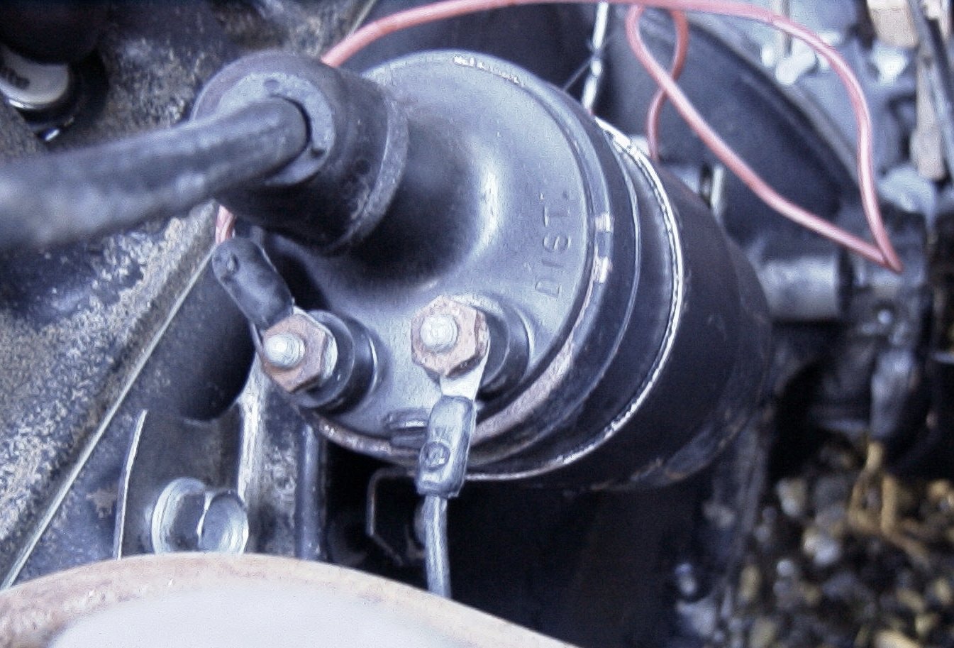
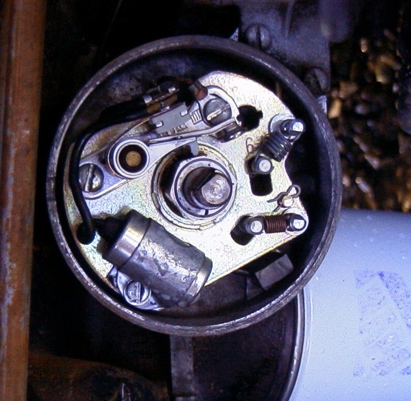
| If you use compressed air to blow out the distributor, be careful around the vacuum advance, as you can easily damage the diaphragm if you blow into the chamber (blue arrow). | I spray a little teflon lubricant on the points plate pivot area after cleaning (see red arrows). I like Tri-Flow. The points plate should pivot smoothly for the vacuum advance to work. |

|
|
|
Cleaned up coil.
|
Remove the negative ("Dist")
lead from the coil; it will not be reused. On this rig, the nut requires a 3/8" socket, nutdriver, or wrench. 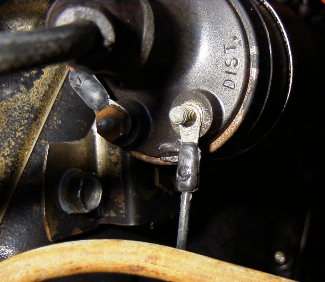
|
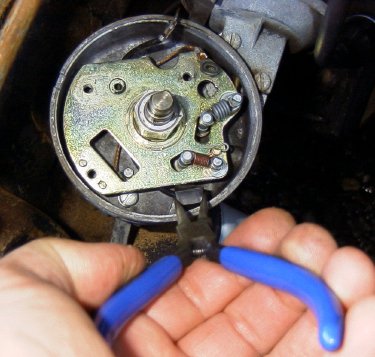
Remove the points & condenser, then pull up on the "Dist" harness
grommet to remove it. Needlenose pliers help for this.
|
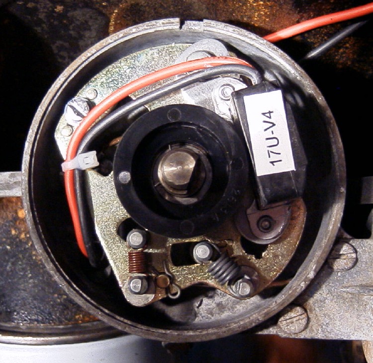
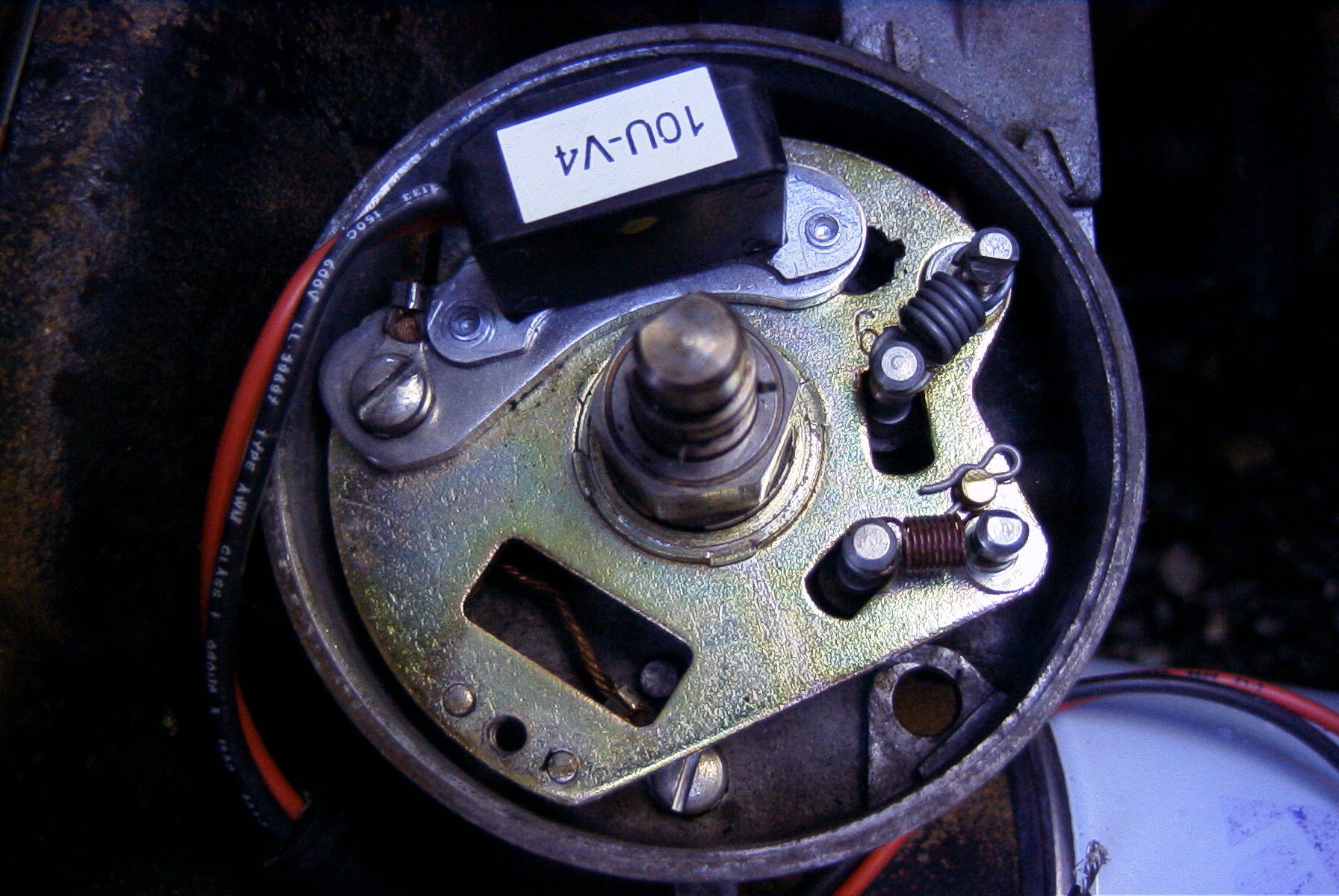
View after removing the old points/condenser/wire harness, and bolting
in the Ignitor. The screw that was on the right end of the points
is not used. The Ignitor has a tit that slips in the old screw hole.
|
New location for the points plate ground lead. Do NOT leave this lead off! It is necessary for the Ignitor to be able to reliably switch the coil to ground. 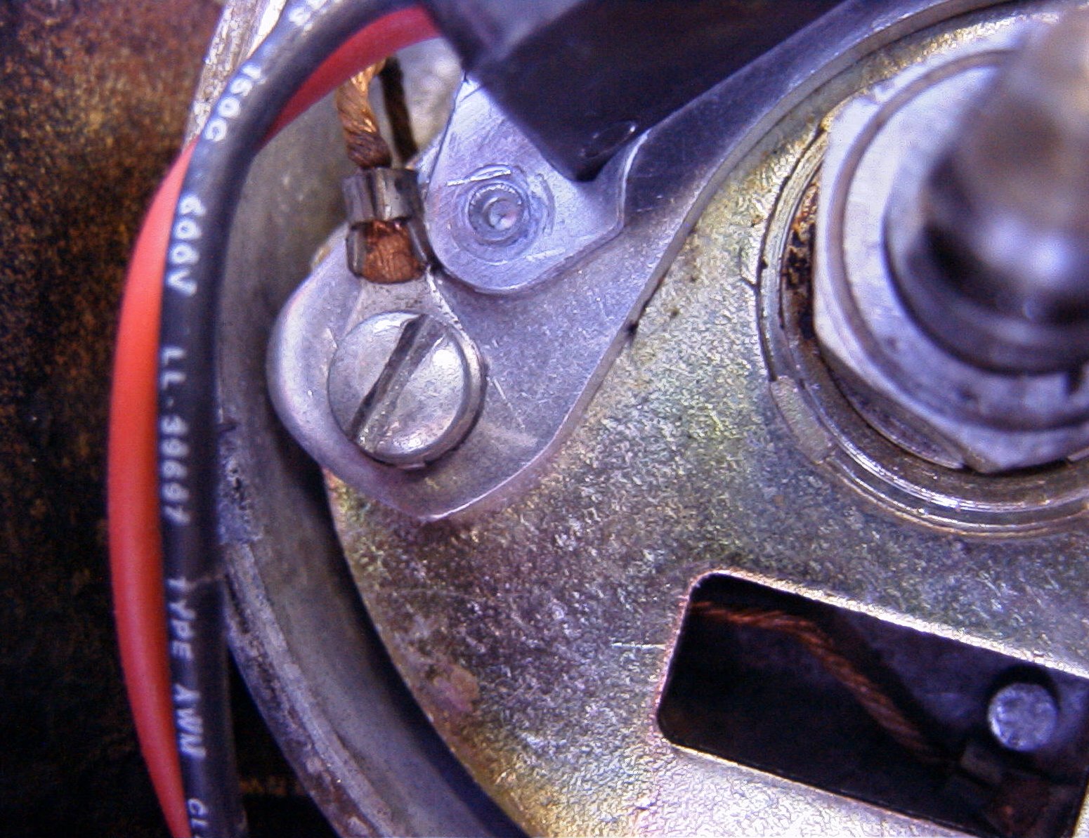
|
As it turns out, my distributor is one that has a different right points screw location, and I am not able to adjust the air gap between the Ignitor and the Magnet Sleeve correctly. Even with the Ignitor adjusted "out" as far as its slot will allow, I cannot get any gap and the Sleeve contacts the Ignitor. A call to Pertronix (I spoke with "Bill" on 19-Jul-00) confirmed that they have had a design change for the Ignitor's base plate, that moves the fixed tit "inward" a bit, which allows the slot to be able to adjust fine. They offered to swap the unit I have for a later production unit.
I decided to file the slot a bit longer, which Bill agreed should work fine. It did work well, but was more work than I felt should have been necessary. Later, I took Pertronix up on their offer, and they sent a newer version of the 1266. For details on the first installation (modifying the Ignitor base plate), go here.
For reference, my distributor No. is C3CF-2127-3EC ('63 Ford Falcon wagon with 170ci Six, no A/C, no PS, built in San Jose and sold in Calif.). Mine is probably the original distributor, but if you have a rebuilt distributor, you could have either style of the points plates installed, regardless of the distributor number.
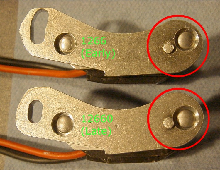
On the Early version shown, the slot has been modified; this is explained here. |
Illustration of the difference between the "early" and "late" 1266
Ignitor. Depending upon which points base plate your distributor
has, you may have to use the later version.

|
Now dress the Ignitor leads. At first I tried to route them under the points plate, but it's difficult to route them so that they don't rub that way. Remember, that plate moves, not very far but often, so for long-term reliability, the leads should rub as little as possible. I found that a nylon tie strap, as shown, combined with careful management of the slack in each run, gave good results. The only section of the leads that flex are between the tie strap and the grommet, and the run between the strap and the Ignitor is restrained low enough to clear the rotor. You won't find any mention of this in the Pertronix installation instructions. |
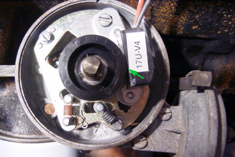
Install the Ignitor, adjust for .030" air gap (green arrow).
|
Next, you'll want to affix a ring terminal (included in the kit) to the black Ignitor lead. Pertronix does not suggest how to do this, though they do supply two solderless connectors. I prefer to solder all connections whenever possible, so I removed the insulating jacket from their ring terminal. The black lead length, as supplied, is nearly perfect. I did not trim it at all for this rig.
I first slipped a section of heat shrink tubing over the lead, then crimped the terminal to the lead (I used a solderless crimping tool, but if you're going to solder it, you can use Vise Grips), then soldered it and finished the shrink. Connect it to the "Dist" or "Neg" terminal of the coill. No pic at this time, but it looks nice.
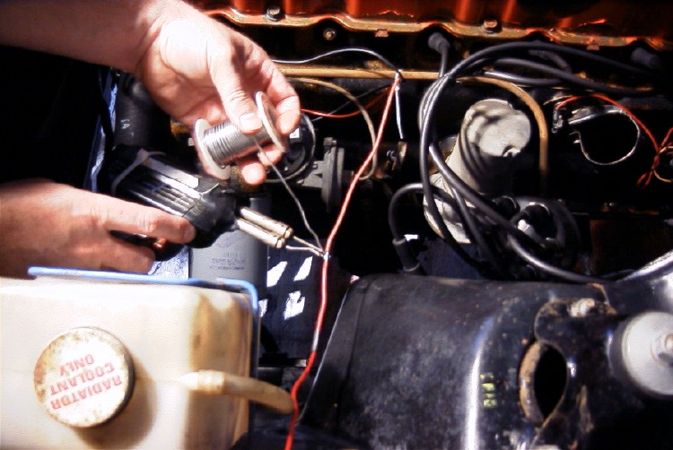
For testing purposes, you can now jumper the Ignitor red lead to the battery positive terminal, and proceed to start and retime the engine. I found that the timing needed a little adjustment; it was a bit advanced. The Timing Tips are here.
|
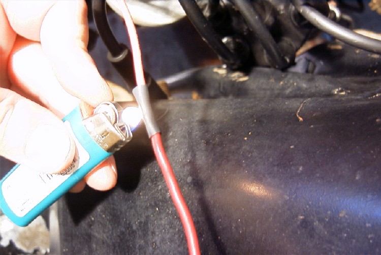
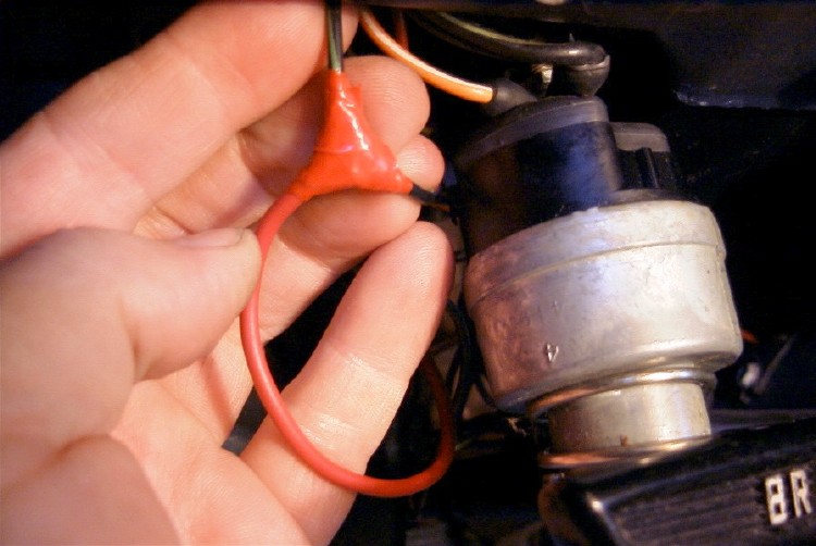
The Ignitor's positive lead needs to be extended by about 6'. I soldered on this extension of red 14ga wire . . . |
| . . . then used some heat-shrink tubing. |
|

|
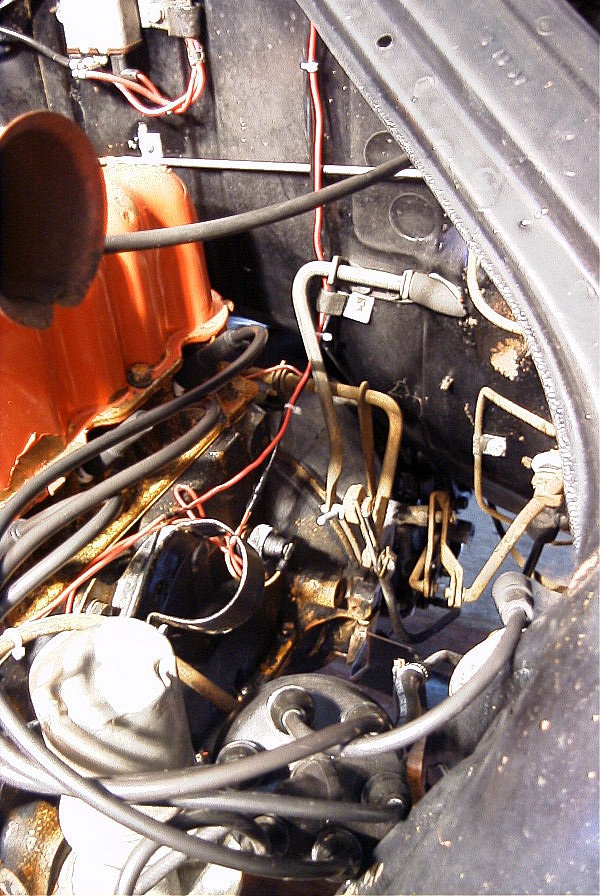
I routed the Ignitor leads on the engine side of the distributor, then used two nylon ties to affix it to the underside of the fuel line. The goal is to reduce vibration and chafing of the leads, and to keep them away from both HV sources and hot things that could damage the insulation. The (relatively) cool, metal fuel line is ideal. |
| The new lead can be tied to to the existing oil pressure switch harness. |
|
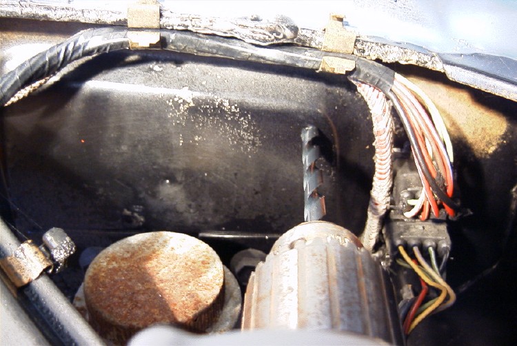
I drilled an 1/8" pilot hole, then a 5/16" hole, to match the grommet's OD.
|

|
|
The grommet installed, and lead in position. |
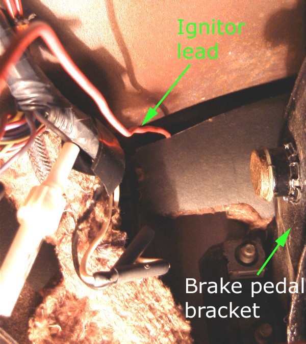
| Underdash view of the new lead. On an AT car, it exits behind some firewall insulation; on a manual transmission car, this would be above the clutch pivot. |
|
|
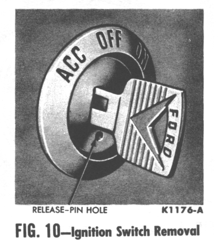
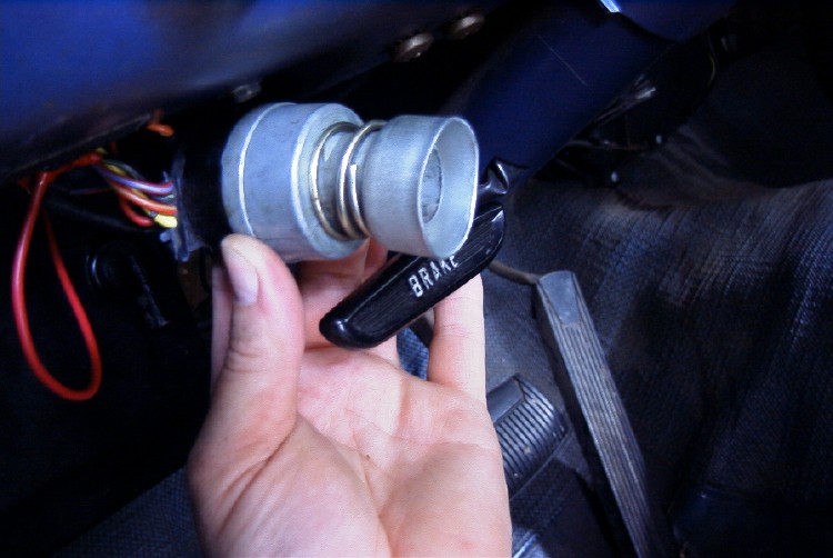
If you haven't yet, disconnect the battery.
Next, remove the ignition switch lock cylinder. Here, I quote the shop manual [notes in brackets are mine]: "Turn the ignition key to the accessory position. Slightly depress [using a bent paper clip] the pin shown in Fig. 10, turn the key counterclockwise, and pull the key and lock cylinder out of the switch assembly. Press in [hard, toward you, toward the dash] on the rear of the switch and rotate the switch 1/8 turn counterclockwise (as viewed from the terminal end). Remove the bezel, switch and spacer [cup]." Oil & Gen lights ON? Disconnect the battery! One more tip: after you remove the lock cylinder, don't fiddle with the lock or turn the bits. It makes it very difficult to reassemble. |
| Armed with that official Ford tidbit, here's a pic of just what you're up against. You have to rotate the switch, because the bezel is keyed to the dash and won't rotate. |
|
|
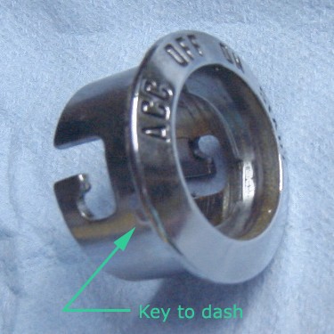
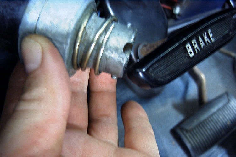
A handy pic of what you're trying to turn. |
| Note this pic carefully for later: when you reassemble the switch/spring/spacer cup to the dash/bezel, the notch should be positioned at about 1 o'clock, or you'll never get the bezel to mate with it. |
|

|
After dropping the ignition switch down for access, you can identify
the B-G (Black w/Green stripe) wire. It feeds the "Oil" and "Gen"
indicators, and is ON only with the key in the "On" or "Start" positions.
Use the B-G wire that is molded into the flat plug. In some cars, there may also be a B-G wire bolted to the Accessory stud in the center of the switch: don't use that one, because it's ON with the key in the Acc. position! |
|
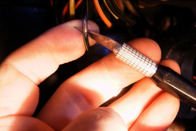
Carefully trim 1/4" of the insulation from the correct B-G wire.
I chose a spot about 3/4" from the plug. I used an Exacto knife,
but a single-edged razor blade or equivalent can be used if an Exacto isn't
handy.
Work the blade all around the wire, and remove the insulation clean around. Use light pressure, or you risk cutting the wire strands. |
|

|
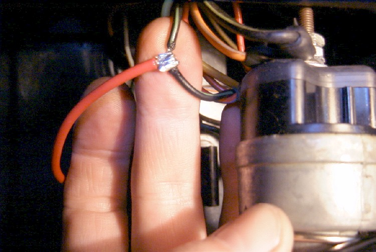
Trim the new Pertronix wire to a comfortable length, then strip it back 3/8". Using needlenose pliers, fold the stripped end into a "U" shape, hook it over the G-B wire's stripped section, and crimp it in place. |
| Solder the new connection. IMO, this is a superior method of connection, to a 3M-style tap. This may corrode, but its resistance will not rise, at least, not until a great number of other things have failed! |
|
|
Tape up the connection. |
Reassemble the ignition switch into the dash, clean up the bits of wire and insulation, and you're done.
|
This site used to be powered by:
|
|
|
Send mail to Al about this page.
Update history:
|
Back to the the Falcon/Comet FAQ