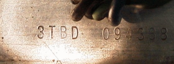
(I don't do audio, so I do a lot of guessing.)

(I don't do audio, so I do a lot of guessing.)
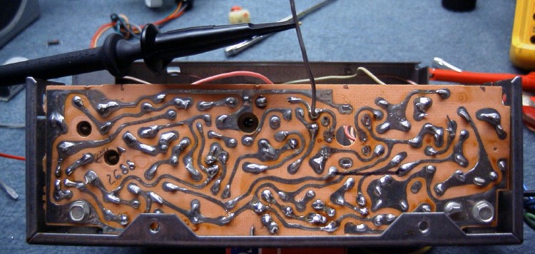
A good location to find the AM signal, is the connection shown below (if the RF/Converter/IF stages are OK).
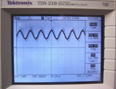
You'll only get a waveform if you've tuned in a station, so watch the 'scope while tuning . . .
|
. . . and when tuned to a strong local station, yields a stable frequency signal, whose amplitude varies. Hey, AM == "Amplitude Modulation", right? |
I checked the IR, Converter, and RF stages and they looked OK . . . up to the input to the audio amp.
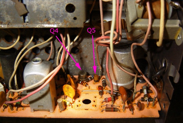
I pulled the first two transistors in the amplifier stage (Q4 & Q5) and they looked good and checked OK, checked a few resistor values, all looked OK, soldered everything 'em back in and lo! All of a sudden, it plays. I *hate* that.
Flake of crud on a pin under one of the transistors? It sure didn't have any cold solder, that's for sure.
View below is of Q4 & Q5 with the IF coil removed for clarity (and
access):
After asking for help on sci.electronics.repair, I got some . . .
Michael A. Terrell <michaelaterrell@netscape.net> had this to offer:
"Early solid state car radios used all germanium transistors. The most common failures were the RF amp, Local oscillator, and the converter (Mixer) transistors. The easiest way to find the bad transistor is to check the collector votages. If you find one that's near zero, the transistor is open. I used to test, find the bad part and repair the radio in less time than the service clerk took to write up the work order, and all I used was a meter, signal tracer, and an old signal generator. Over 95% of the failures were open transistors, and the replacement parts weren't critical Something rated for RF in the low ECG numbers worked very well."Well, open transistors are not terribly common on the monitors I've repaired (different tech, different era, no germanium stuff), so I am grateful for this advice from someone who's been there.
After two days' running on the bench, the radio is still running fine, but I think I'll just replace all the transistors on the mainboard (Q1 through Q4), because I don't want to pull this again for a while, and they're probably cheap. Q4 (NTE/ECG102A, 2N109) is almost certainly where the problem was.
Q5 is a silicon part, not germanium, so I didn't replace it. Its modern equivalent is a 2N2222, which is not an especially trouble-prone part unless overloaded, and certainly doesn't go intermittent.
I've added the ECG equivalents to the originals, in green, to the schematic below, which is for the 4BTD ('64).
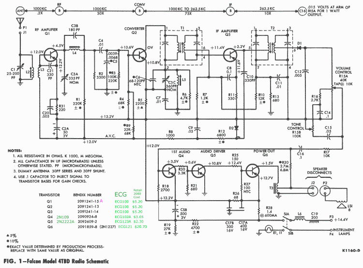
I was unable to use the NTE100 to replace Q2; the old Q2 works OK, but subbing the NTE100 yields no output. This must be one of those circuits in which the NTE "equivalent" isn't.
|
|
|
|
| Send mail to Al about this page. |
Last updated 14-Mar-2001
|
Back to the Falcon/Comet FAQ