Click on most images to view a larger version
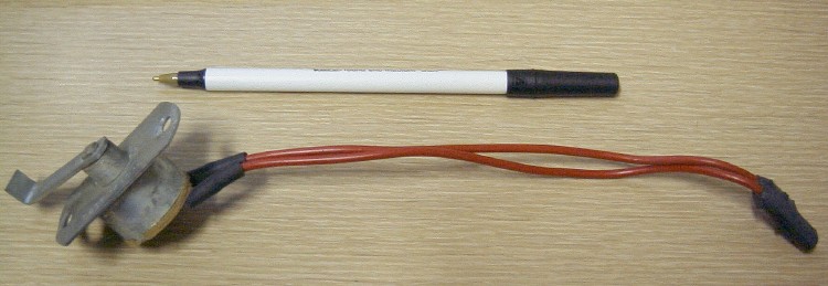
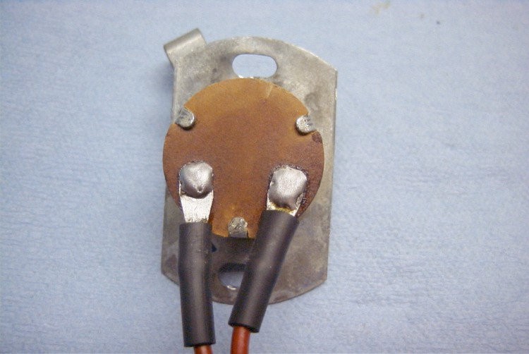
On early wagons, the (optional) electric rear window uses a switch to inhibit raising the window if the tailgate is open. This switch, somewhat misleadingly labelled by Ford as a Limit Switch, is located in the tailgate's jamb, on the right side. The one I'm working with here is from a '63, and the number on this switch is C0DF-14A011-C.

If your window will lower via both the dash switch and the key switch on the tailgate, but won't raise using either, suspect the Limit Switch. To test:
| 1) | Remove the spare tire cover and tire, jack and accessories in the well. | ||||
| 2) | Locate the wire harness connectors to the rear of the spare tire. | ||||
| 3) |
Disconnect the harness which has two Red wires on one side, and three
Red wires on the other
(connector 44A). It's supposed to be the black connector (others are blue, red, or white). |
||||
|
4) |
|
||||
| 5) |
Raise the tailgate and try both the dash switch and the key switch
at the tailgate. If the window now operates normally, or at least
goes up now, you have a defective Limit Switch.
|
| '61-62 Tailgate (190k) (2197w) | '63 Tailgate (69k) (750w) | |
| '63 Tailgate (464k) (2513w) |
Removal: remove the two 5/16" hex head self-tapping screws which retain the switch to the jamb, and remove it, feeding the 7" harness up through its mounting hole.
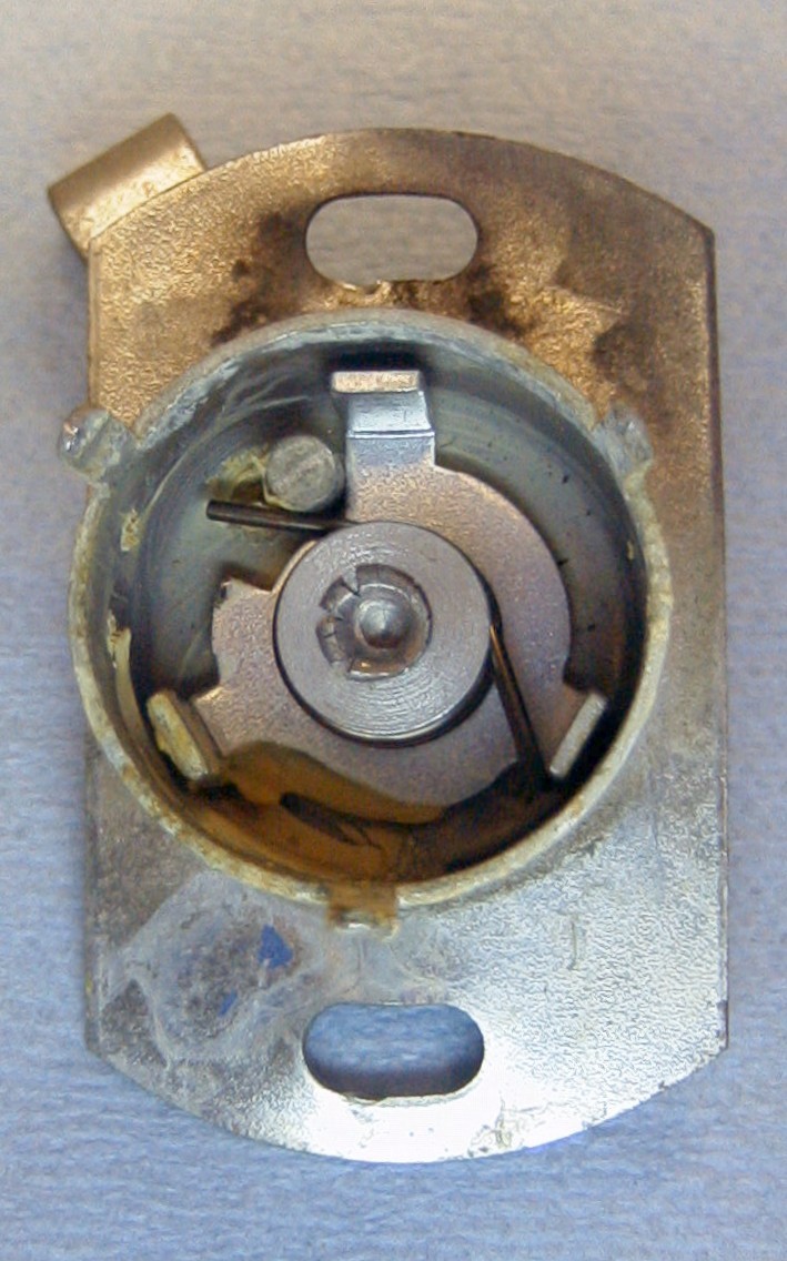
You may not be able to find a suitable replacement. You can often "recondition" the switch as an alternative. It's constructed very much like an ignition switch, but with fewer parts to lose! Because the Limit Switch's contacts never switch a load (that is, it isn't making or breaking the circuit when the window motor is actually running), the contacts will have almost no electrical wear from arcing, only corrosion from the elements. Unlike a faulty ignition switch, you stand a good chance of success in repairing the Limit Switch.
First, clean the the exteriour. I use aerosol carburetor cleaner, but brake cleaner would be OK as well. Avoid water-based cleaners like 409, Simple Green and the like. Not for electrical reasons, but because the lead board for the switch is a kind of fibreboard, which can absorb water and swell. It will dry, but it's best not to wet it. In addition, if that lead board gets wet, it's much easier to break it; it becomes somewhat mushy, and it's harder to solder the fixed contacts with a wet lead board.
Note the orientation of the leads to the arm for later reassembly. You may want to scratch a match mark in the lead board and housing, but as you can only assemble it three ways, you could also just use the above pic as a guide.
Using pliers (needlenose or standard), carefully bend the lead board's
retaining tabs straight up. Do not bend "back". You only get
a limited number of bends on these tabs before they fatigue and snap.
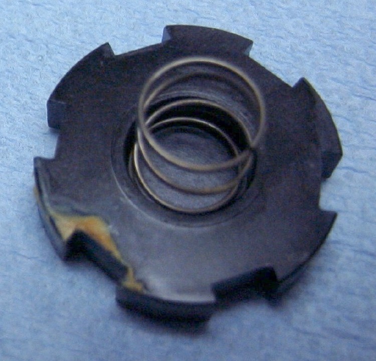
Lift the lead board off the housing, then remove the moveable contact (brass)
and carrier (black plastic). There is a compression spring
(3/8"OD x 3/8" free length) under the carrier; it's not under a lot of
pressure, but don't lose it anyway!
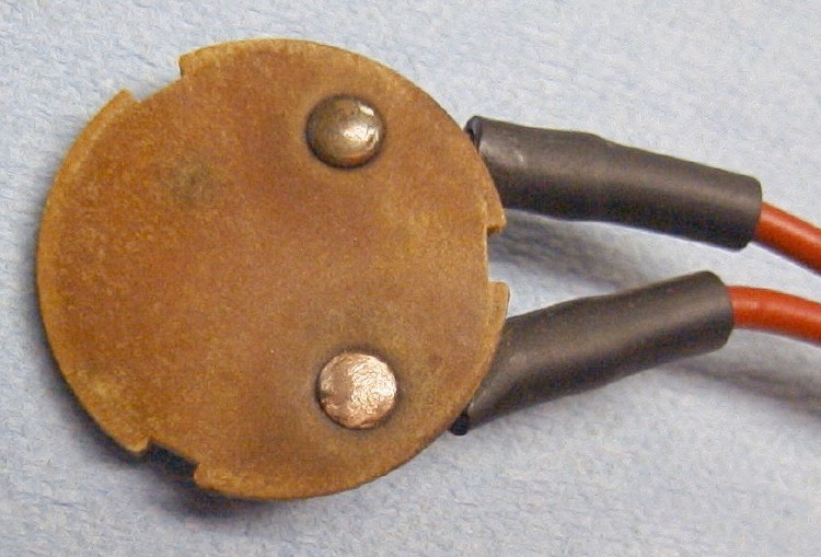
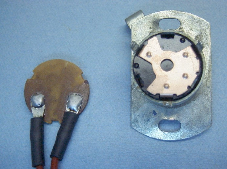
Solder terminals
|
One of the problems that occur with these is that the ring terminals
are riveted to the contacts. This doesn't work so well, because the
lead board will compress, and the ring terminals can work side to side,
creating a loose connection, generating heat, and further deteriorating.
Clean the area around each terminal with an abrasive; I used a flexible emery fingernail board; fine sandpaper is a good choice also. Using a fairly hot iron (750°+) and plenty of rosin flux, solder the ring terminals to the contacts. You can safely get this quite a bit hotter than when working with PCBs and other electronics. Take your time, let the flux work on the accumulated corrosion under the rivet head. Use a flux remover when it's cooled. In a pinch, "Goof Off" hand cleaner will work. |
Upper terminal is "after" soldering and defluxing.

Lower terminal is "before". |
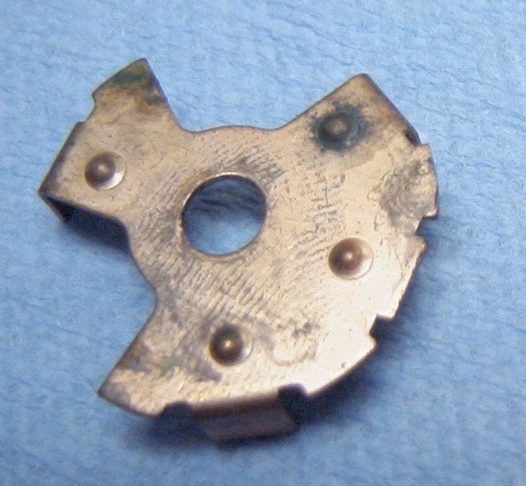
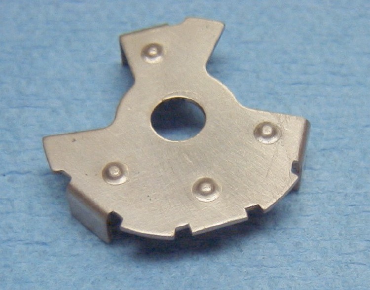
Clean Fixed Contacts
|
Upper contact is "before".
|
Next, clean/abrade the fixed contacts. Once again, I used an emery board. These contacts often are just a bit corroded, and little material needs to be removed to make them like new. Don't get too exuberant and grind off too much. Wipe off any abrasive dust when you're through. |
Clean Moveable Contacts
|
You can see that this is where the real damage has occurred.
The contact at the upper right is corroded.
Use a toothbrush, water, and your favorite surfactant to clean it. I used "Bar Keeper's Friend", and it took less than a minute of scrubbing to polish it up. Any old fine abrasive will probably work: Zud, Comet, Ajax, maybe even toothpaste, though it might take more polishing time. |
|
After polishing. |
Bottom (housing side) of the moveable contact carrier. |
Clean & Lubricate Housing
| The housing may or may not need cleaning, depending upon where it's been and in what weather. This one is clean, and only needs a bit of relubrication. I use Tri-Flow teflon lubricant (in non-aerosol 2oz bottle with applicator, be sure to shake before using) for the center pivot, and LubriPlate white grease for the contacts area. You don't need much grease, the only sliding friction is the contacts themselves. |
|
Assemble & Grease Moveable Contacts into Housing
Ready to grease and assemble.
Put dab of grease on each "tit" on the moveable contact plate.
|
To assemble the moveable contact plate, carrier, and spring in the
housing, assemble the plate/carrier/spring, hold the housing upside down,
and offer the plate/carrier/spring up to the housing. Or find another
way <g>.
Make certain that the orientation of the arm and moveable contact plate are as shown, or the switch will not work correctly! |
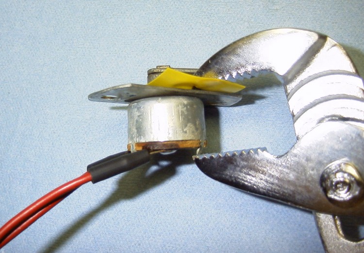
Assemble Housing
| I found that 8" Channel Lock pliers work very well to rebend the retaining tabs. The yellow tape is applied to prevent the tool from scratching through the plating, and allowing rust to form. |
|
Assembly Complete
|
Use a continuity checker, ohmmeter, or any other low-voltage (<50v) test tool you can find, to check electrical and mechanical operation. With the arm in the position shown, no current should flow (light off, no meter deflection, whatever). Moving the arm to the right, against spring pressure, should activate your (light, meter, whatever). |
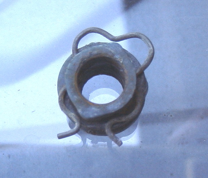
While testing the bypassed Limit Switch, I found the reason for the rear window jamming on the right side: someone had popped the right door lift nylon roller off of its pin. I've heard that this is very common for the door lift rollers.
To access the tailgate's guts, you must remove the inner skin. Unfortunately, there are two problems:
1) The tailgate end hinged support straps bolt to the inner skin, so when you remove them (and then the skin), the tailgate is prevented from swinging down and hitting the bumper only by the gate springs, which isn't much. You must be extremely careful to not press down on the tailgate while it's disassembled, or you will end up with a crease in the outer skin.
2) Once the hinged support straps are removed, there are thirteen 10-32 Phillips-head screws retaining the inner skin to the shell, that must be removed. These are likely to be very rusty, and others have reported that they have a tendency to break off. Be prepared to helicoil one or more of them if the heads look very rusty. I was lucky, and didn't lose a one.
Be sure to lubricate all the retaining screws before reassembly!
You may want to use Lock-tite blue compound on the hinged strap pivot bolts
-- mine are special nylock bolts (the threaded area is cross-drilled and
has a patch of nylon inserted, to help prevent the pivot from backing out).

|
|
| I removed & retensioned the metal spring clip, then greased the lift arm pivot and the roller, slid the roller into the lift channel, then repositioned the glass and popped the roller over the lift arm pivot. |
|
After applying grease, be sure and insert the roller into the lift channel with the clip "down", not as shown. |
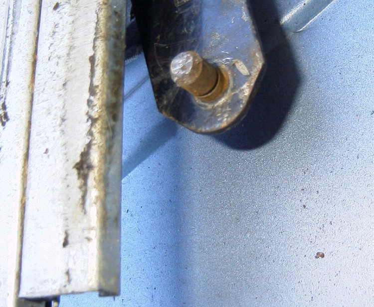
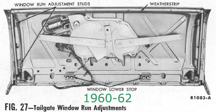
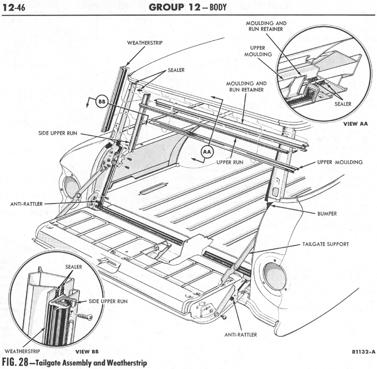
The weatherstrip's retaining screws are "under" the tailgate glass. To access the weatherstrip retaining screws, remove the window stop(s):
1960-62: two stops, one centered on each side, at the lower edge of
the glass, retained by two 1/2" head bolts.
1963-on: a single stop in the center, at the lower edge of the glass,
retained by two 1/2" head bolts.
After the stop(s) is/are removed, you can use the key switch to lower
the window an extra 1/2", and can then access the fixed weatherstrip's screws.
|
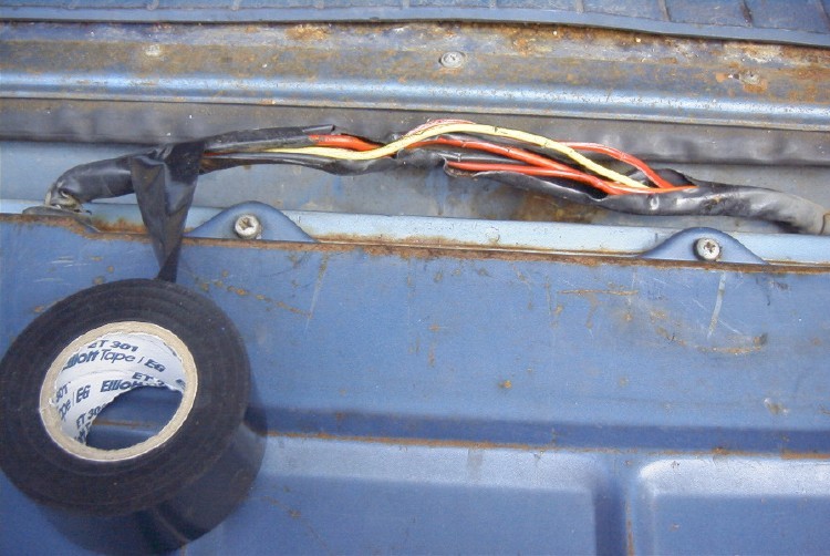
The previous owner had not been able to raise the rear window (because
the Limit Switch was corroded) and had wired in a bypass switch.
He'd slit open the harness to attach the switch. I'm using special
harness wrap tape here to rewrap it. This is Elliot 301 tape; it
is non-adhesive, like Saran Wrap, stretchy & clingy. I've
repaired and rebuilt several wiring harnesses using this or similar products.
Avoid using electrical tape for harness wrap, because it tends to move, especially in hot climates, leaving a sticky, slimy mess. I'm sure you can think of examples you've seen! This wrap tape typically is available in 3/4" & 1" widths. This particular roll I purchased from Clark's Corvair Parts a couple of years ago. This product can be difficult to locate. |
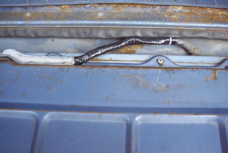
| After "repairs". I find that I can't "tie" the loose end when I do these, so I keep the wrap from unwrapping by using a nylon tie strap instead. No mess, looks good. |
|
Back to the Falcon/Comet FAQ index